

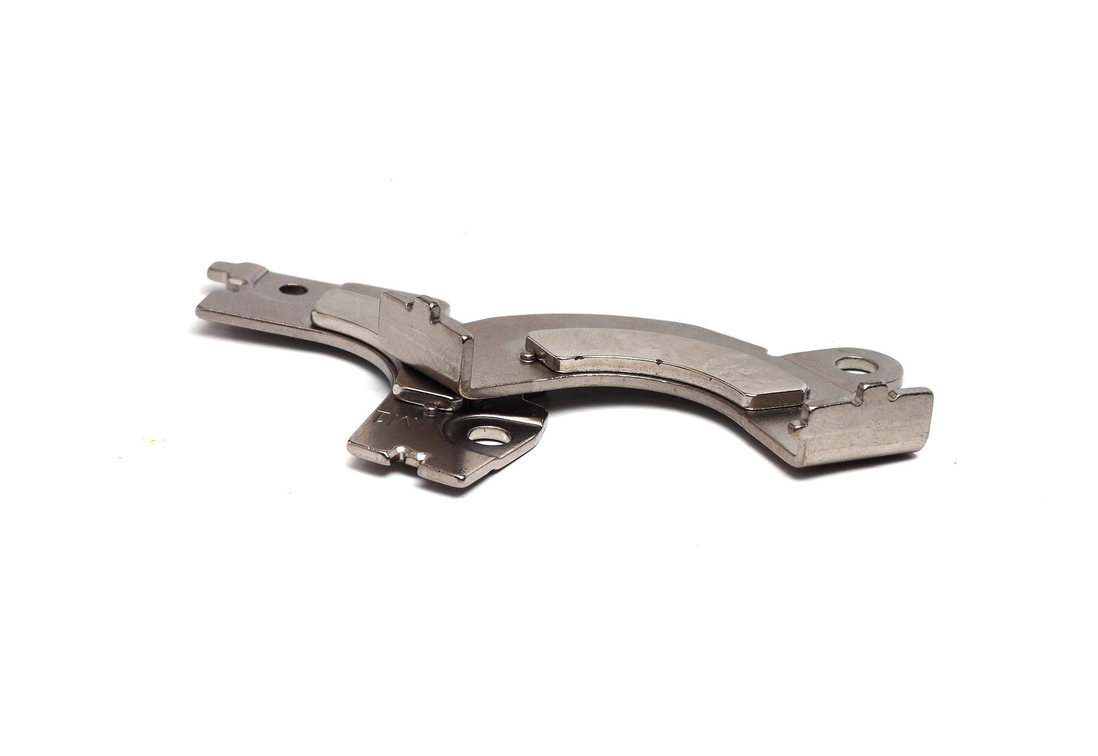
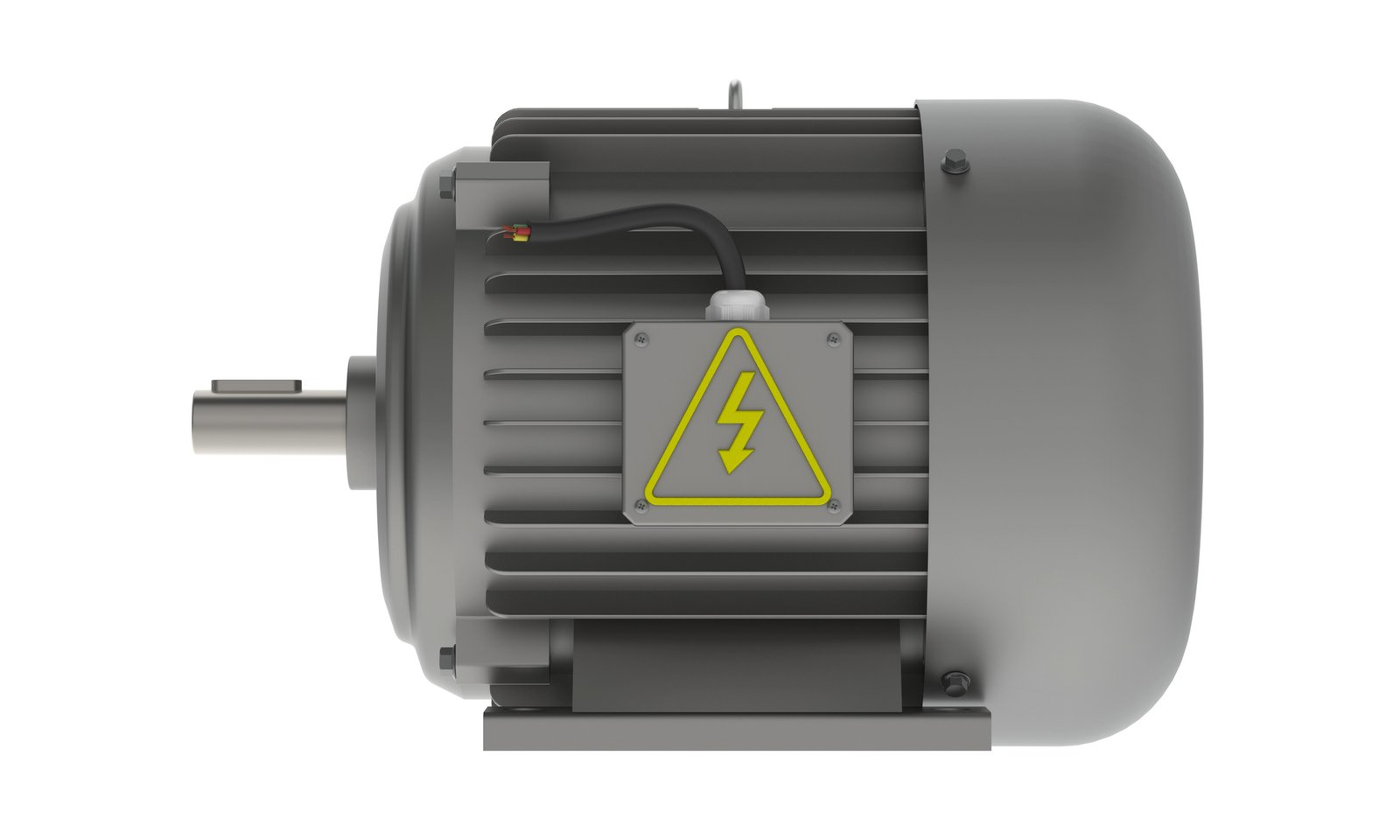
Life-cycle assessment of a single 1.25-MW Adjustable Permanent Magnet Drive.
Rank 03 · NdFeB application
Large industrial permanent-magnet drive
A-MMeasured/teardown valuePublished design/BOM case
In the rotor or permanent-magnet coupling of the drive system studied. The design and system boundary must be established from the technical documentation.
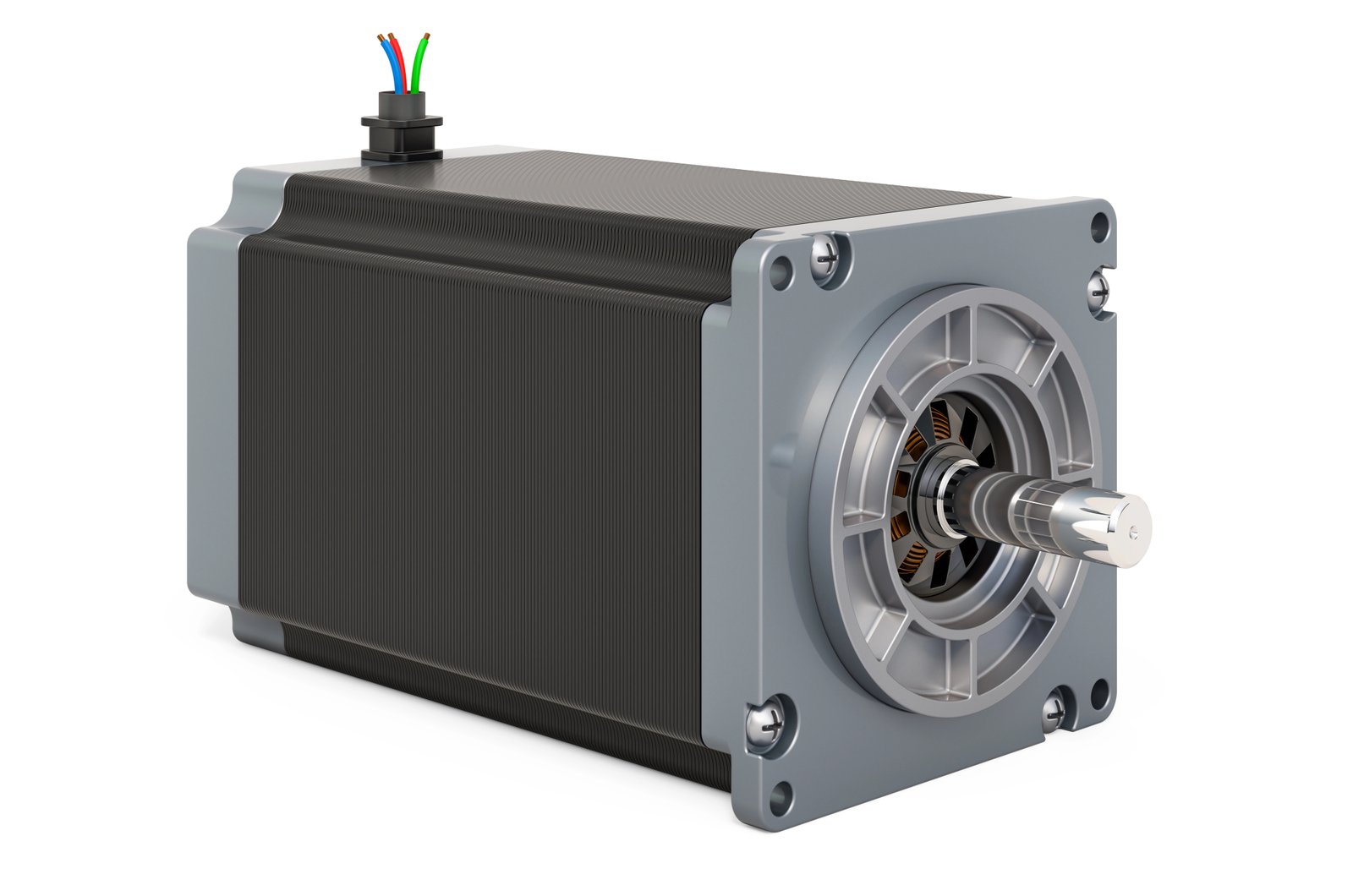
Reference value72 kgNdFeB in the 1.25-MW design studied
Highest reference value used72 kgNdFeB in the 1.25-MW design studied
Limitations of the figure
This design case is not a market average for industrial drives of other power ratings, designs or manufacturers.
Original application & recovery
Where the magnets are located in the industrial drive
Its position within the device helps with identification, but does not in itself establish the alloy, weight or eligibility for purchase.
Location within the equipment
In the rotor or permanent-magnet coupling of the drive system studied. The design and system boundary must be established from the technical documentation.
System boundary
NdFeB in the 1.25-MW design studied. Foreign parts, housings, shafts, back irons, supports and other device components are not automatically included in the magnet mass.
Record before submitting an enquiry
- Photograph the nameplate, power rating and motor design
- Describe the rotor, coupling and other metals separately
- State any operating fluids and the dismantling status
Source reference
Source of the figure
A-MMeasured/teardown value
Sustainability · LCA of a 1.25 MW Adjustable Permanent Magnet Drive
Life-cycle assessment of a single 1.25-MW Adjustable Permanent Magnet Drive.
Open original source ↗Other applications